In today’s world, ensuring the security of your home or office has become more crucial than ever. With rapid advancements in smart technology, building an effective and affordable intrusion alert system is now within reach. This project leverages popular microcontrollers such as Arduino or ESP32 to integrate multiple sensors-like PIR motion detectors and door/window contact sensors- into a cohesive system that monitors for unauthorized activity in real time. When a breach is detected, an audible alert is triggered by a buzzer or alarm module, immediately notifying occupants and potentially deterring intruders.
This system is designed not only for simplicity and reliability but also for scalability and integration into larger home automation setups. By harnessing the quick response of PIR sensors, which detect the heat signatures of moving objects, alongside door/window sensors that monitor the opening and closing of access points, the device provides comprehensive coverage for your security needs. The microcontroller continuously processes sensor data, allowing for prompt and precise responses to any suspicious behavior, ensuring that no potential threat goes unnoticed.
Furthermore, the design prioritizes user-friendliness and flexibility. With an uncomplicated wiring setup and clear, concise code, even those new to electronics can build and deploy the system with minimal hassle. Its modular nature means that it can be easily expanded or modified, such as by adding wireless connectivity for remote alerts or integrating additional sensors to cover larger areas. Emphasizing both proactive monitoring and immediate alert mechanisms, this intrusion alert system is a testament to how modern technology can offer practical, real-world solutions to enhance everyday security.
Components Required
- Arduino Uno or ESP32
- PIR Sensor (Passive Infrared Sensor)
- Door/Window Contact Sensors
- Buzzer or Alarm Module
- Jumper Wires
- Breadboard
- Power Supply (Battery or USB Power)
Circuit Diagram
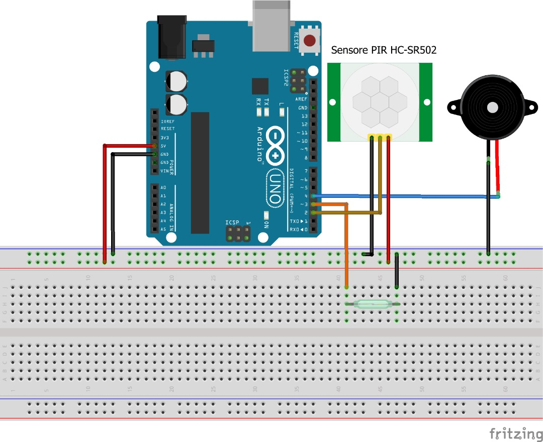
Component Connections
- Connecting the PIR Sensor to the Controller
The PIR sensor detects motion by sensing infrared radiation changes. It typically features three pins: VCC, GND, and OUT (signal). - VCC (Power Input): Connect to the 5V pin on the Arduino/ESP32.
- GND (Ground): Connect to the common ground on the board.
- OUT (Signal): Connect to a digital input pin (e.g., D2) on the controller.
- Wiring the Door/Window Contact Sensors
These sensors monitor the opening and closing of doors or windows and usually operate in a normally closed (NC) configuration. - Sensor Terminal: Connect one terminal to a digital input pin (e.g., D3) on the controller.
- Pull-Up Resistor: Use the internal pull-up resistor (or add an external one) to keep the line high when the sensor is closed.
- Ground Connection: Connect the other terminal to GND.
- Connecting the Buzzer or Alarm Module
The buzzer provides an audible alert when an intrusion is detected. - Positive Terminal: Connect to a digital output pin (e.g., D4) on the controller.
- Negative Terminal: Connect to GND.
Powering the System
For optimal performance, ensure that both the microcontroller and sensors receive stable power. The Arduino/ESP32 can be powered via a USB connection or a dedicated battery pack.
- Important: Avoid connecting high-voltage power sources directly to sensor inputs; always adhere to the recommended voltage levels for each component.
Installing the Components
- Sensor Placement: Secure the PIR sensor in a position where it can effectively monitor the desired area. Mount the door/window sensors at the entry points to detect any breaches.
- Buzzer Positioning: Place the buzzer in a location where the sound can be heard clearly, serving as an immediate alert signal.
Uploading the Code to the Controller
- Open your Arduino IDE or equivalent development environment.
- Copy the provided code into a new sketch.
- Connect your Arduino or ESP32 to your computer via a USB cable.
- Select the appropriate board and port.
- Upload the code to the device.
CODE
|
CODE EXPLANATION
Setting Up the Pins:
- const int pirSensorPin = 2;
We make a label called "pirSensorPin" that equals 2. This tells the computer that the PIR motion sensor (which detects movement) is connected to pin number 2. - const int doorSensorPin = 3;
This creates a label "doorSensorPin" that equals 3. It tells the computer that the door or window sensor is connected to pin number 3. - const int buzzerPin = 4;
Here, we set up "buzzerPin" to be 4. This tells the computer that the buzzer (the part that makes the alarm sound) is connected to pin number 4.
2. The Setup Function:
- void setup() { ... }
This part is like getting everything ready when the computer first turns on. It only happens one time. - Inside setup():
- pinMode(pirSensorPin, INPUT);
This tells the computer to listen for signals from the PIR sensor on pin 2. It sets the sensor pin as an input, which means the sensor sends information into the computer. - pinMode(doorSensorPin, INPUT_PULLUP);
This tells the computer to listen on pin 3 for the door sensor. The "INPUT_PULLUP" means the computer uses an extra helper (a resistor) that keeps the signal high unless the door is opened. - pinMode(buzzerPin, OUTPUT);
This sets pin 4 as an output. Now, the computer can send a signal to the buzzer to make it sound when needed. - Serial.begin(9600);
This starts a way for the computer to send messages to a screen (like a monitor). It helps us see what's happening inside the code (this is useful for checking or "debugging" the system).
- pinMode(pirSensorPin, INPUT);
The Loop Function:
"void loop() { ... }
- This part is like the computer's repeating checklist. It goes through these instructions over and over, checking if anything needs to happen.
"Inside loop():
- bool motionDetected = digitalRead(pirSensorPin);
The computer checks pin 2 to see if the PIR sensor detects any motion (like someone moving) and saves that answer as either true (yes) or false (no) in a box called "motionDetected." - bool breachDetected = (digitalRead(doorSensorPin) == LOW);
The computer checks pin 3 to see if the door sensor shows that a door or window is open. If it reads "LOW" (like a signal saying "open"), it saves true in a box called "breachDetected." - if (motionDetected || breachDetected) { ... } else { ... }
This line says: "If either the motion sensor detects movement or the door sensor shows an open door, then do the stuff in the first bracket. Otherwise, do the stuff in the second bracket."
- bool motionDetected = digitalRead(pirSensorPin);
- Inside the if block:
- digitalWrite(buzzerPin, HIGH);
The computer sends a signal on pin 4 to turn the buzzer on. This makes the alarm sound to warn of an intrusion. - Serial.println("Alert: Intrusion Detected!");
The computer prints a message on the screen that says, "Alert: Intrusion Detected!" so you know something unusual is happening.
- digitalWrite(buzzerPin, HIGH);
- Inside the else block:
- digitalWrite(buzzerPin, LOW);
If no movement or open door is detected, the computer sends a signal to turn the buzzer off, keeping things quiet.
- digitalWrite(buzzerPin, LOW);
- delay(100);
This tells the computer to wait for 100 milliseconds (a very short pause) before checking everything again. This pause helps the system work smoothly.
How It Works Together
The system continuously monitors for any changes in the sensor outputs. When the PIR sensor detects movement or a door/window sensor registers a breach, the microcontroller immediately activates the buzzer. This immediate alert not only informs occupants of a potential security threat but also acts as a deterrent. Serial messages further aid in debugging and monitoring system status in real time.
Common Problems and Solutions
- False Alarms:
Cause: Sensitivity of the PIR sensor may be set too high.
Solution: Adjust sensor placement or implement software filtering to ignore minor disturbances. - Sensor Malfunction:
Cause: Poor wiring or loose connections can lead to unreliable sensor readings.
Solution: Double-check all connections and ensure that the sensors are securely mounted.
- Insufficient Power:
Cause: Power fluctuations may affect sensor performance.
Solution: Use a regulated power supply or battery pack that meets the voltage requirements of all components.
Conclusion
This intrusion alert system demonstrates an effective approach to home or office security by leveraging simple yet powerful components. By combining the real-time monitoring capabilities of PIR and contact sensors with an immediate audible alert, the system provides a robust solution for detecting unauthorized entry. Its modular design and straightforward code make it an ideal project for anyone interested in enhancing security with microcontroller-based projects.