In today's world, robots are no longer confined to factories or research labs—they are becoming an essential part of homes, offices, and industrial spaces. One fascinating example is the wall-following robot, a compact and intelligent machine designed to navigate along walls while maintaining a consistent and safe distance.
Instead of relying on complex pre-mapped routes, this robot uses an ultrasonic sensor to measure its distance from the wall in real time. By continuously adjusting its path based on sensor feedback, it ensures smooth movement, even as the environment changes. This simple yet effective navigation method allows the robot to operate efficiently in tight spaces, hallways, and structured environments.
Wall-following robots have practical applications in warehouses, hospitals, and autonomous cleaning systems, where precise movement is crucial. They demonstrate the power of sensor-driven decision-making, motor control, and real-time adjustments, which are fundamental concepts in robotics.
This project offers a hands-on introduction to robotic navigation, embedded systems, and control algorithms, making it an excellent learning experience for those interested in automation and intelligent machines. By the end, you’ll have built a functional robot capable of autonomously following walls with accuracy and efficiency.
Components Required
- Arduino Uno
- Ultrasonic Sensor (HC-SR04)
- DC Motors
- Motor Driver (L298N)
- Battery (9V or similar)
- Wheels
- Jumper Wires
- Breadboard
- Robot Chassis
Circuit Diagram
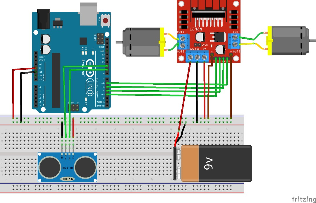
Component Connections
Connecting the Ultrasonic Sensor to Arduino
The ultrasonic sensor (HC-SR04) is key to detecting the wall’s distance. It uses sound waves to measure how far objects are from the sensor. Communication with the Arduino is achieved through digital signals.
Wiring the HC-SR04 to the Arduino:
- VCC (Power Input): Connect to the 5V pin on the Arduino to power the sensor.
- GND (Ground): Connect to the Arduino’s GND.
- TRIG (Trigger Pin): Connect to a designated digital pin (e.g., D9) on the Arduino.
- ECHO (Echo Pin): Connect to another digital pin (e.g., D10) on the Arduino.
Why use these digital pins?
They allow the Arduino to send a trigger pulse and then listen for the echo, making it possible to calculate the distance based on the time delay.
Connecting the Motor Driver to Arduino
A motor driver module bridges the Arduino with the DC motors. It empowers the microcontroller to modulate the motors’ speed and direction via PWM signals, ensuring smooth motion adjustments.
Wiring the Motor Driver to the Arduino:
- IN1 & IN2 (Motor 1 Control Pins): Connect to two digital output pins on the Arduino (e.g., D3 and D4) for controlling Motor 1’s direction.
- IN3 & IN4 (Motor 2 Control Pins): Connect to two other digital output pins (e.g., D5 and D6) for controlling Motor 2.
- ENA & ENB (Enable Pins): Connect to PWM-capable pins on the Arduino to adjust motor speed.
- VCC (Motor Driver Power Input): Connect to 5V for the logic circuitry.
- GND (Ground): Ensure a common ground by connecting to the Arduino’s GND.
- DC Motors: Attach the motor wires to the corresponding terminals on the motor driver.
Why include a motor driver?
The Arduino alone cannot provide sufficient current to drive motors, so the motor driver amplifies the power while allowing precise control over speed and direction.
Powering the System
To guarantee reliable operation, both the Arduino and motors must receive stable power.
Powering the Motors:
- Battery (e.g., 9V): Connect the battery’s positive terminal to the motor driver’s power input, and the negative terminal to the common ground.
Powering the Arduino:
- Use a USB cable or an external power source (such as a power bank) to supply the Arduino.
Important: Never connect the battery directly to the Arduino’s 5V pin; instead, use the VIN pin to take advantage of the onboard voltage regulator.
Installing the Components on the Robot
- Mounting the Ultrasonic Sensor:
Secure the HC-SR04 on the robot chassis using screws or adhesive. Position it facing the wall to obtain accurate distance measurements. - Setting Up the Motors and Motor Driver:
Attach the DC motors to the wheels and ensure they are firmly mounted on the chassis. Connect the motors to the driver, verifying the correct wiring for forward and turning maneuvers. - Final Assembly:
Assemble all components on the chassis, making sure wiring is neatly routed and secure to prevent disconnections during movement.
Uploading the Code to the Arduino
- Open the Arduino IDE on your computer.
- Copy and paste the provided code into a new sketch.
- Connect your Arduino to the computer using a USB cable.
- Select the correct board and port in the Arduino IDE.
- Click the Upload button to transfer the code to the Arduino.
Once uploaded, the Arduino begins reading distance data from the ultrasonic sensor and adjusts the motors’ operation accordingly to maintain a consistent distance from the wall.
CODE
// Wall-Following Robot Code // Define ultrasonic sensor pins const int trigPin = 9; const int echoPin = 10; // Define motor control pins for two motors const int motor1Pin1 = 3; const int motor1Pin2 = 4; const int motor2Pin1 = 5; const int motor2Pin2 = 6; const int motorSpeed = 200; // Adjust motor speed as necessary long duration; int distance; void setup() { // Initialize sensor pins pinMode(trigPin, OUTPUT); pinMode(echoPin, INPUT);
// Set motor pins as outputs pinMode(motor1Pin1, OUTPUT); pinMode(motor1Pin2, OUTPUT); pinMode(motor2Pin1, OUTPUT); pinMode(motor2Pin2, OUTPUT);
// Start serial communication for debugging Serial.begin(115200); } void loop() { // Clear the trigger pin digitalWrite(trigPin, LOW); delayMicroseconds(2);
// Send a 10-microsecond pulse to trigger the sensor digitalWrite(trigPin, HIGH); delayMicroseconds(10); digitalWrite(trigPin, LOW);
// Read the echo pin and calculate the duration of the pulse duration = pulseIn(echoPin, HIGH);
// Convert the duration into distance (in centimeters) distance = duration * 0.034 / 2; Serial.print("Distance: "); Serial.println(distance);
// Adjust the robot's movement based on distance measurements if (distance < 20) { // Too close to the wall: steer right turnRight(); } else if (distance > 30) { // Too far from the wall: steer left turnLeft(); } else { // Optimal distance: move forward moveForward(); }
delay(50); } void moveForward() { digitalWrite(motor1Pin1, HIGH); digitalWrite(motor1Pin2, LOW); digitalWrite(motor2Pin1, HIGH); digitalWrite(motor2Pin2, LOW); } void turnRight() { // Slow down or reverse left motor to steer right digitalWrite(motor1Pin1, LOW); digitalWrite(motor1Pin2, LOW); digitalWrite(motor2Pin1, HIGH); digitalWrite(motor2Pin2, LOW); } void turnLeft() { // Slow down or reverse right motor to steer left digitalWrite(motor1Pin1, HIGH); digitalWrite(motor1Pin2, LOW); digitalWrite(motor2Pin1, LOW); digitalWrite(motor2Pin2, LOW); } void stopMotors() { digitalWrite(motor1Pin1, LOW); digitalWrite(motor1Pin2, LOW); digitalWrite(motor2Pin1, LOW); digitalWrite(motor2Pin2, LOW); } |
CODE EXPLANATION
1. Global Definitions and Variable Declarations
// Wall-Following Robot Code |
This indicates that the following code is for a wall-following robot project.
// Define ultrasonic sensor pins const int trigPin = 9; // The digital pin used to trigger the ultrasonic sensor const int echoPin = 10; // The digital pin used to read the echo response from the sensor |
- const int trigPin = 9;
Declares a constant integer named trigPin and assigns it the value 9. This pin sends a pulse to trigger the ultrasonic sensor. - const int echoPin = 10;
Declares a constant integer named echoPin and assigns it the value 10. This pin reads the returning echo pulse from the sensor.
// Define motor control pins for two motors const int motor1Pin1 = 3; // Motor 1 control pin 1 const int motor1Pin2 = 4; // Motor 1 control pin 2 const int motor2Pin1 = 5; // Motor 2 control pin 1 const int motor2Pin2 = 6; // Motor 2 control pin 2 |
- These lines define the digital pins connected to the motor driver that control the two motors. Each motor has two control pins to manage direction.
const int motorSpeed = 200; // Adjust motor speed as necessary |
- Defines a constant integer for motor speed. (Note: In the provided code, this variable is defined but not directly used in motor control commands.)
long duration; // Variable to store the time duration of the ultrasonic pulse int distance; // Variable to store the calculated distance in centimeters |
- long duration;
Declares a variable to store the time (in microseconds) that the echo pulse is received. - int distance;
Declares a variable to hold the computed distance based on the sensor's duration measurement.
2. Setup Function
void setup() { // Initialize sensor pins pinMode(trigPin, OUTPUT); // Set the trigger pin as an output pinMode(echoPin, INPUT); // Set the echo pin as an input
// Set motor pins as outputs pinMode(motor1Pin1, OUTPUT); // Configure motor 1 pin 1 as output pinMode(motor1Pin2, OUTPUT); // Configure motor 1 pin 2 as output pinMode(motor2Pin1, OUTPUT); // Configure motor 2 pin 1 as output pinMode(motor2Pin2, OUTPUT); // Configure motor 2 pin 2 as output
// Start serial communication for debugging Serial.begin(115200); // Initialize serial monitor at 115200 baud rate } |
- Inside setup():
- pinMode(trigPin, OUTPUT);
Configures the trigger pin to send signals. - pinMode(echoPin, INPUT);
Configures the echo pin to receive signals. - Motor Pin Configuration:
Each motor control pin is set as an OUTPUT so that the Arduino can send control signals to the motor driver. - Serial.begin(115200);
Initializes serial communication. This allows you to view sensor data (like distance) on the serial monitor for debugging purposes.
- pinMode(trigPin, OUTPUT);
3. Main Loop Function
void loop() { // Clear the trigger pin digitalWrite(trigPin, LOW); // Ensure the trigger pin is low before sending a pulse delayMicroseconds(2); // Wait 2 microseconds to stabilize the pin state
// Send a 10-microsecond pulse to trigger the sensor digitalWrite(trigPin, HIGH); // Set the trigger pin high to start the pulse delayMicroseconds(10); // Keep it high for 10 microseconds (duration required by the sensor) digitalWrite(trigPin, LOW); // Set the trigger pin low to end the pulse
// Read the echo pin and calculate the duration of the pulse duration = pulseIn(echoPin, HIGH); // Measure the time (in microseconds) until the echo pin goes low
// Convert the duration into distance (in centimeters) distance = duration * 0.034 / 2; // Calculate distance using speed of sound (0.034 cm/µs), divided by 2 for the round trip Serial.print("Distance: "); Serial.println(distance); // Print the calculated distance to the serial monitor
// Adjust the robot's movement based on distance measurements if (distance < 20) { // If too close to the wall (less than 20 cm) turnRight(); // Execute a right turn to increase the distance } else if (distance > 30) { // If too far from the wall (more than 30 cm) turnLeft(); // Execute a left turn to decrease the distance } else { // If the distance is within the desired range (20-30 cm) moveForward(); // Continue moving forward }
delay(50); // Small delay to allow the sensor and motors to update smoothly } |
- Triggering the Sensor:
- digitalWrite(trigPin, LOW);
Ensures the trigger pin starts low. - delayMicroseconds(2);
Waits briefly to stabilize the signal. - digitalWrite(trigPin, HIGH);
Sends a high pulse to the sensor. - delayMicroseconds(10);
Maintains the high state for 10 microseconds, which is the required pulse duration. - digitalWrite(trigPin, LOW);
Ends the pulse by setting the pin low.
- digitalWrite(trigPin, LOW);
- Reading the Sensor:
- duration = pulseIn(echoPin, HIGH);
Measures the duration that the echo pin stays high (time taken for the pulse to return). - distance = duration * 0.034 / 2;
Converts the time into distance using the formula:
Distance (cm)=Duration×0.034 cm/µs2\text{Distance (cm)} = \frac{\text{Duration} \times 0.034 \, \text{cm/µs}}{2}Distance (cm)=2Duration×0.034cm/µs
(Division by 2 accounts for the travel to the wall and back.) - Serial.print("Distance: "); and Serial.println(distance);
Print the measured distance to the serial monitor for debugging.
- duration = pulseIn(echoPin, HIGH);
- Movement Control Logic:
- if (distance < 20)
Checks if the robot is too close to the wall. If true, it calls turnRight() to adjust its course. - else if (distance > 30)
Checks if the robot is too far from the wall. If true, it calls turnLeft() to bring it closer. - else
If the distance is within the optimal range (20–30 cm), it calls moveForward() to continue on its path.
- if (distance < 20)
- delay(50);
Provides a short delay before the next loop iteration, ensuring stable sensor readings and smooth motor operation.
4. Motor Control Functions
a. Moving Forward
void moveForward() { digitalWrite(motor1Pin1, HIGH); // Set Motor 1 to move forward digitalWrite(motor1Pin2, LOW); // Ensure Motor 1 is not running in reverse digitalWrite(motor2Pin1, HIGH); // Set Motor 2 to move forward digitalWrite(motor2Pin2, LOW); // Ensure Motor 2 is not running in reverse } |
- Function: Activates both motors to drive the robot straight ahead.
- Sets one control pin of each motor high and the other low to achieve forward motion.
b. Turning Right
void turnRight() { // Slow down or stop the left motor to pivot right digitalWrite(motor1Pin1, LOW); // Stop Motor 1 (assumed to be the left motor) digitalWrite(motor1Pin2, LOW); // Ensure Motor 1 remains off digitalWrite(motor2Pin1, HIGH); // Run Motor 2 (assumed to be the right motor) forward digitalWrite(motor2Pin2, LOW); // Ensure Motor 2 is not in reverse } |
- Function: Causes the robot to steer right by reducing or stopping the left motor while keeping the right motor active.
c. Turning Left
void turnLeft() { // Slow down or stop the right motor to pivot left digitalWrite(motor1Pin1, HIGH); // Run Motor 1 (assumed to be the left motor) forward digitalWrite(motor1Pin2, LOW); // Ensure Motor 1 is not in reverse digitalWrite(motor2Pin1, LOW); // Stop Motor 2 (assumed to be the right motor) digitalWrite(motor2Pin2, LOW); // Ensure Motor 2 remains off } |
- Function: Causes the robot to steer left by keeping the left motor active and stopping the right motor.
d. Stopping the Motors
void stopMotors() { digitalWrite(motor1Pin1, LOW); // Turn off Motor 1 digitalWrite(motor1Pin2, LOW); // Ensure both control pins for Motor 1 are low digitalWrite(motor2Pin1, LOW); // Turn off Motor 2 digitalWrite(motor2Pin2, LOW); // Ensure both control pins for Motor 2 are low } |
- Function: Halts both motors by setting all control pins to LOW, effectively stopping any movement.
How It Works Together
- Sensor Activation:
The ultrasonic sensor is triggered by a short pulse. It then listens for the echo, and the time taken is used to calculate the distance to the wall. - Real-Time Decision Making:
The main loop continuously reads the distance and decides:
- If too close: The robot will steer right to move away.
- If too far: It steers left to get closer.
- If within range: It continues straight ahead.
- Motor Commands:
The functions (moveForward(), turnRight(), and turnLeft()) convert the sensor data into precise motor actions, ensuring the robot follows the wall at a steady distance. - Feedback Loop:
The combination of constant sensor readings and immediate motor adjustments creates a feedback loop that keeps the robot aligned parallel to the wall, even if the wall’s distance changes.
Common Challenges and Solutions
Inaccurate Distance Measurements:
- Challenge:
The ultrasonic sensor might give erratic readings due to interference or misalignment. - Solution:
Ensure the sensor is mounted securely and pointed directly toward the wall. Adding a small delay or averaging multiple readings can also help stabilize the measurements.
- Challenge:
Incorrect Motor Response:
- Challenge:
The robot might not turn as expected if the wiring to the motor driver is incorrect. - Solution:
Double-check the wiring between the Arduino, motor driver, and motors. Verify that each motor is connected to the correct pins and that the driver is receiving proper power.
- Challenge:
Delayed or Jittery Movement:
- Challenge:
Rapid changes in sensor data can cause the robot to jitter or respond too quickly. - Solution:
Adjust the delay (e.g., delay(50)) in the loop to give the motors time to respond smoothly. For more advanced control, consider implementing a PID controller to smooth out the adjustments.
- Challenge:
Serial Communication Issues:
- Challenge:
If the serial monitor isn’t displaying data correctly, debugging can be difficult. - Solution:
Ensure that Serial.begin(115200) matches the baud rate in your serial monitor and check all USB connections.
- Challenge:
Conclusion
The wall-following robot brings together simple components to create something surprisingly intelligent. With just an ultrasonic sensor, a couple of motors, and an Arduino, this project shows how real-time feedback and basic control logic can be used to make a robot navigate its environment smoothly and independently.
It’s not just about building something that moves—it’s about understanding how sensors and motors can work together through code to make smart decisions. From detecting distance to adjusting direction, every part of this robot plays a role in maintaining that perfect path along the wall.
This project is more than a technical exercise—it’s a great way to get hands-on with embedded systems, robotics, and automation. By the end, you’re not only left with a working robot but also with practical experience in problem-solving, circuit design, and real-time control. It’s a simple build, but one that opens the door to more advanced and creative robotic projects.